











How mooring loads determine Floating Platform anchor design
How Mooring Loads Determine Floating Platform Anchor Design
Mooring loads are not a secondary calculation added after a Floating Platform has been selected. They are one of the inputs that determine whether the platform can remain on station, maintain workable equipment alignment, and continue operating safely through changing water levels, currents, wind, waves, and production conditions. For dredging and mining applications, anchor design must account for both environmental loading and the forces generated by the work itself.
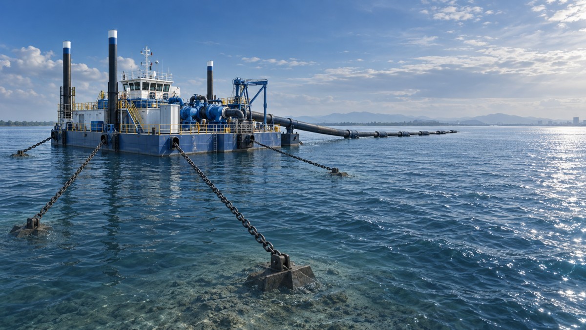
A platform carrying pumps, screening equipment, processing modules, dredging machinery, fuel systems, or discharge pipelines is rarely a passive floating body. Cutter reaction, pipeline drag, onboard lifting, material accumulation, and changing draft can all alter the tension distribution in its mooring system. The anchor arrangement must therefore be evaluated as part of the complete operating system rather than as an isolated seabed or riverbed component.
The Load Path Starts Above the Waterline
Anchor sizing begins with a clear load path: environmental forces act on the hull, superstructure, equipment, pipelines, and exposed material; those forces create movement and line tension; line tension is transferred through fairleads, padeyes, shackles, chain, wire rope, synthetic rope, and connectors before reaching the anchor and surrounding soil. Weakness at any point can limit the allowable holding capacity of the entire system.
Wind loading is often more significant than expected when a platform supports tall conveyors, control cabins, gantries, pipe racks, or processing equipment. Current loading may dominate in rivers, canals, and dredging cuts, especially where the hull presents a broad frontal area. In exposed water, wave-induced drift and cyclic line loading must also be considered. A design based only on average conditions may appear adequate in calm water but lose station-keeping margin when gusts, vessel wake, or seasonal flow changes occur.
The maximum mooring load is not always created by the strongest wind or fastest current alone. Combined directions matter. A cross-current with moderate wind can create an oblique loading condition that overloads one corner line, shifts the working heading, or introduces undesirable yaw. Technical evaluation should therefore review load cases by direction, not merely a single resultant force.
Why Platform Motion Changes Anchor Requirements
A mooring system is designed not only to resist force but also to control motion. Allowable surge, sway, yaw, heave, roll, and pitch depend on the work being performed. A mineral-processing platform may tolerate some horizontal excursion if pipelines remain within their bending and connection limits. A dredging platform working near a defined excavation line may require tighter position control. If piles, spuds, ladders, suction pipes, or discharge lines are operating, even modest movement can affect productivity or cause mechanical interference.
This is why two platforms with similar displacement may need very different anchors. A lightly loaded barge in sheltered water can use a relatively compliant catenary arrangement, where chain weight and geometry absorb movement. A platform that must hold a precise heading may need a stiffer configuration, more lines, different lead angles, or supplementary spud positioning. Increased stiffness, however, normally raises peak line and anchor loads. The preferred solution is not automatically the system with the least movement; it is the system that keeps motion within operational limits without imposing impractical loads on equipment or ground conditions.
The Inputs That Should Be Confirmed Before Anchor Selection
A credible anchor proposal needs more than platform length and water depth. Technical reviewers should request the information that drives the analysis:
- Platform lightship weight, operating displacement, draft, freeboard, and projected windage area;
- Equipment arrangement, onboard payload variation, lifting operations, and expected center-of-gravity changes;
- Design wind, current, wave, water-level, and vessel-wake conditions for the actual site;
- Water depth range, bank geometry, available mooring radius, navigation constraints, and pipeline routing;
- Soil investigation data, including sediment depth, bearing layers, shear strength, density, or rock conditions where applicable;
- Mooring line type, diameter, length, pretension, connection hardware, and allowable working limits;
- Required positional accuracy during production, maintenance, shutdown, and emergency conditions.
Missing soil data is a frequent source of false confidence. Anchor holding capacity depends on the interaction between the anchor and the ground, not only on anchor mass. Soft silt, loose sand, dense sand, clay, gravel, weathered rock, and layered riverbeds behave differently. A large conventional deadweight anchor may be workable where deployment simplicity is the priority, yet it can require substantial mass and still provide limited resistance to horizontal drag in weak sediments. Drag embedment anchors, helical anchors, driven piles, drilled anchors, gravity bases, and spud systems each have site-specific strengths and limitations.
Anchor Type Must Match the Direction of Demand
The direction of line pull at the anchor is as important as the calculated tension. Catenary moorings tend to apply a predominantly horizontal load at the anchor when sufficient line lies on the bed. Taut or semi-taut systems can introduce a greater vertical component. An anchor that performs well under horizontal drag may not provide the same capacity when uplift increases. This distinction should be visible in the calculation basis and not buried in a generic equipment schedule.
Anchor layout also affects load sharing. Symmetrical four-point arrangements are widely used because they can provide restraint in several directions, but symmetry on a drawing does not guarantee equal tension in operation. Unequal line lengths, varying water depths, different anchor soil conditions, platform offset, and installation tolerances can shift most of the load to one or two lines. The design should identify the governing line under each environmental and operational case, then check its hardware and anchor capacity accordingly.
For platforms that work along a channel, a spread mooring layout may interfere with passing traffic or discharge pipelines. In those cases, a combination of anchors and spuds, or a controlled repositioning method, may be more practical than maximizing anchor spread. The engineering decision is operational as well as structural.
Operational Loads Are Often Underestimated
Dredging and mineral recovery operations introduce loads that are not present on a simple service pontoon. A floating discharge line can pull laterally as the platform changes heading. A suction ladder can create reaction forces during excavation. Material buildup may change draft and trim. Pump start-up, cutter engagement, winch operation, and lifting activity can create transient loads that are not represented by a static environmental calculation.
The same reasoning applies at the shoreline transition. Equipment selected for wetland restoration, canal maintenance, flood prevention, or shallow construction may need to alternate between floating and grounded work modes. For example, an Amphibious Dredger can travel on tracks over land and operate in water, while hydraulic tilting spuds and side pontoons support stability during deep-water excavation. Its deployment method may reduce dependence on separate launch vessels, but its anchoring or spud arrangement still needs to reflect soil bearing conditions, excavation forces, and local water-level variation.
Checking the System, Not Just the Anchor
A suitable holding capacity does not make the system safe if the chain, wire rope, shackle, fairlead, bollard, or deck reinforcement is undersized. Connections are especially vulnerable because they may experience wear, side loading, corrosion, abrasion, or fatigue from repeated platform movement. Inspection access should be considered during design. An anchor buried beyond reach may be acceptable, but line terminations, fairleads, and winch drums must remain inspectable and maintainable during the operating campaign.
Where a project specifies a recognized marine, civil, or local authority standard, the selected design method, load combinations, safety factors, and inspection requirements should be aligned with that requirement. It is not good practice to assume that an offshore mooring approach transfers directly to a shallow inland mining pond, or that a temporary dredging spread has the same criteria as a permanent floating installation. Site jurisdiction, project duration, consequence of failure, and access for recovery all influence the appropriate basis of design.
A Practical Review Before Mobilization
Before installation, evaluators should confirm the anchor coordinates, line lengths, expected pretension, water level used for setup, and intended operating envelope. The installation team should know which lines are critical, how tension will be checked, and what conditions require re-tensioning or suspension of work. A mooring plan without a practical monitoring method is incomplete, particularly where water levels change quickly or production forces vary through the shift.
Qingzhou Yongli Mining And Dredging Machinery Co., Ltd., established in 1997 in Qingzhou, Shandong Province, works across dredging vessels, floating production platforms, mining equipment, installation, commissioning, and project-operation support. For equipment combinations involving dredgers, pump barges, work boats, transport barges, or processing platforms, the useful starting point is a shared definition of the operating loads and site constraints—not a preselected anchor type.
The final anchor design should show a traceable connection between environmental conditions, operational loads, platform motion limits, mooring-line capacity, and ground holding capacity. If that connection cannot be explained clearly, the design may still be a concept rather than a dependable working arrangement.
